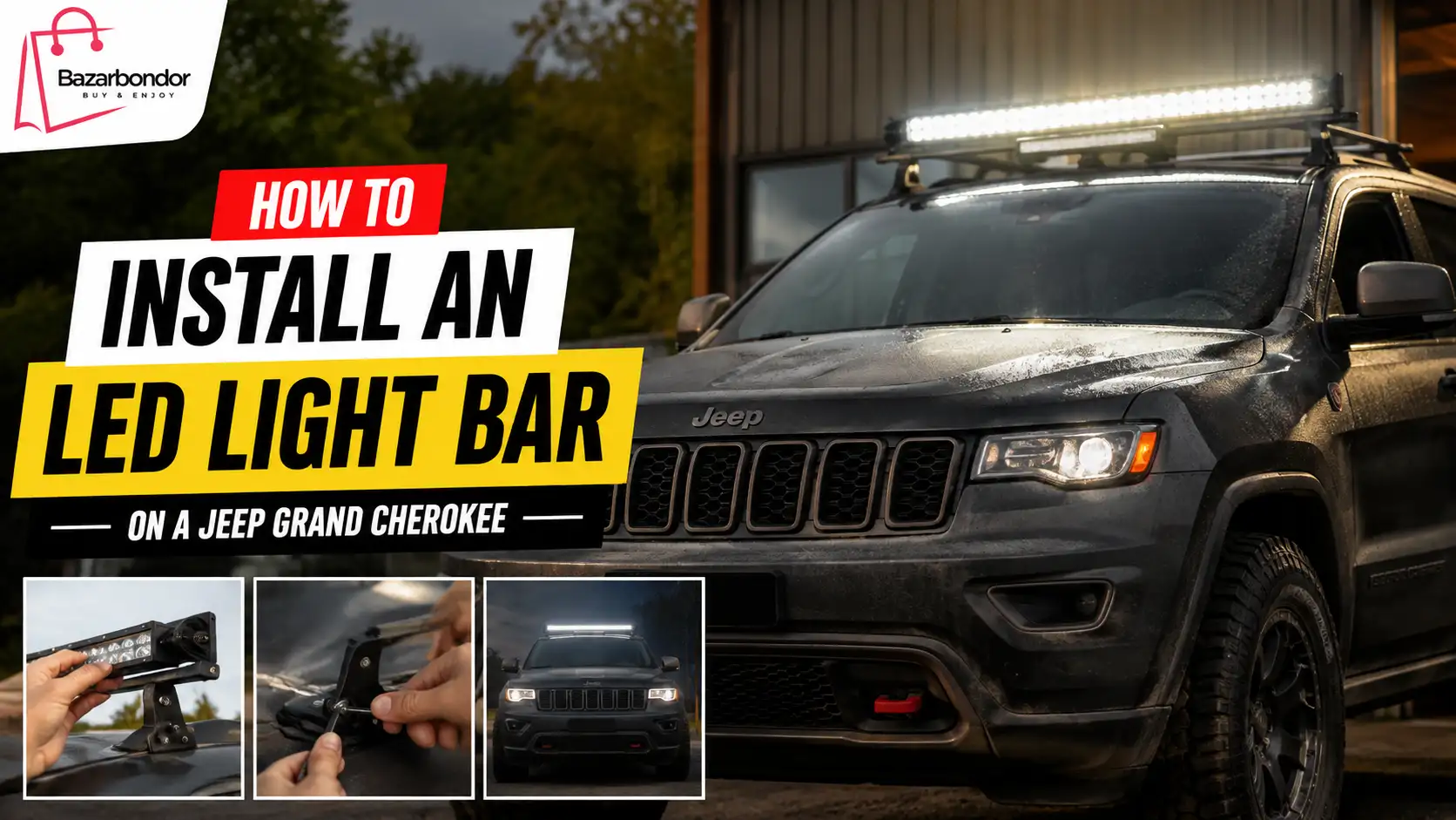
Installing an LED light bar on a Jeep Grand Cherokee involves three main jobs: securely mounting the light, connecting it through a properly fused wiring system, and placing a switch or high-beam trigger inside the vehicle.
A straightforward bolt-on installation can take approximately two to four hours. Allow more time if you must remove the front fascia, fabricate brackets, drill mounting holes, or diagnose a complex electrical system. One vehicle-specific 20-inch WK2 bumper-mount kit, for example, estimates an installation time of approximately two to three hours.
The exact procedure depends on your Grand Cherokee generation, trim level, mounting location, light-bar wattage, and switching method. Before purchasing parts or cutting wires, confirm that the light bar and brackets fit your exact model year.
Important: This guide explains a common auxiliary-light installation. Your light bar, wiring harness, switch, and Jeep may require different connections. Follow the instructions supplied with your equipment and consult a qualified automotive electrician when the correct connection cannot be verified.
Quick Installation Overview
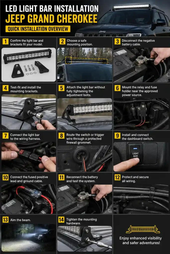
To install an LED light bar on a Jeep Grand Cherokee:
- Confirm the light bar and brackets fit your model.
- Choose a safe mounting position.
- Disconnect the negative battery cable.
- Test-fit and install the mounting brackets.
- Attach the light bar without fully tightening the adjustment bolts.
- Mount the relay and fuse holder near the approved power source.
- Connect the light bar to the wiring harness.
- Route the switch or trigger wire through a protected firewall grommet.
- Install and connect the dashboard switch.
- Connect the fused positive lead and ground cable.
- Reconnect the battery and test the system.
- Protect and secure all wiring.
- Aim the beam and tighten the mounting hardware.
Confirm Your Jeep Grand Cherokee Generation
Jeep Grand Cherokee models use different body structures, bumper designs, electrical systems, battery locations, sensors, and trim fasteners. Identify whether your vehicle is a:
- ZJ
- WJ
- WK
- WK2
- WL
- Grand Cherokee L
Do not order a bracket based only on a listing that says “fits Jeep Grand Cherokee.” Confirm the exact model year, trim, bumper style, tow-hook configuration, grille opening, and mounting width.
Two Grand Cherokees from the same generation may still need different mounting solutions because one may have parking sensors, adaptive cruise-control hardware, a front camera, tow hooks, active grille components, or an aftermarket bumper.
Before installation, inspect the intended mounting area for:
- Radiator and intercooler airflow
- Parking sensors
- Adaptive cruise-control radar
- Front camera visibility
- Tow-hook access
- Recovery points
- Grille shutters
- Wiring harnesses
- Washer-fluid lines
- Air-conditioning components
- Structural bumper supports
Never mount the bar where it blocks cooling airflow, obscures required vehicle lighting, interferes with a safety sensor, or prevents access to a recovery point.
How to Choose the Right LED Light Bar
The best light bar is not automatically the brightest or widest model. It must physically fit the Jeep, provide a useful beam pattern, and operate within the capacity of the wiring system.
Select the Correct Size
Measure the available opening before ordering. Check both:
- The total housing width
- The distance between the mounting points
A light advertised as a “20-inch bar” may have a wider overall housing once the side brackets are installed.
Smaller bars are normally easier to position behind a lower grille, near a license plate, or between bumper openings. Larger bars may require a roof rack, aftermarket bumper, bull bar, or custom brackets.
A vehicle-specific 20-inch bracket system is available for certain WK2 models, showing why exact-year fitment matters more than relying on a universal size description.
Choose a Beam Pattern
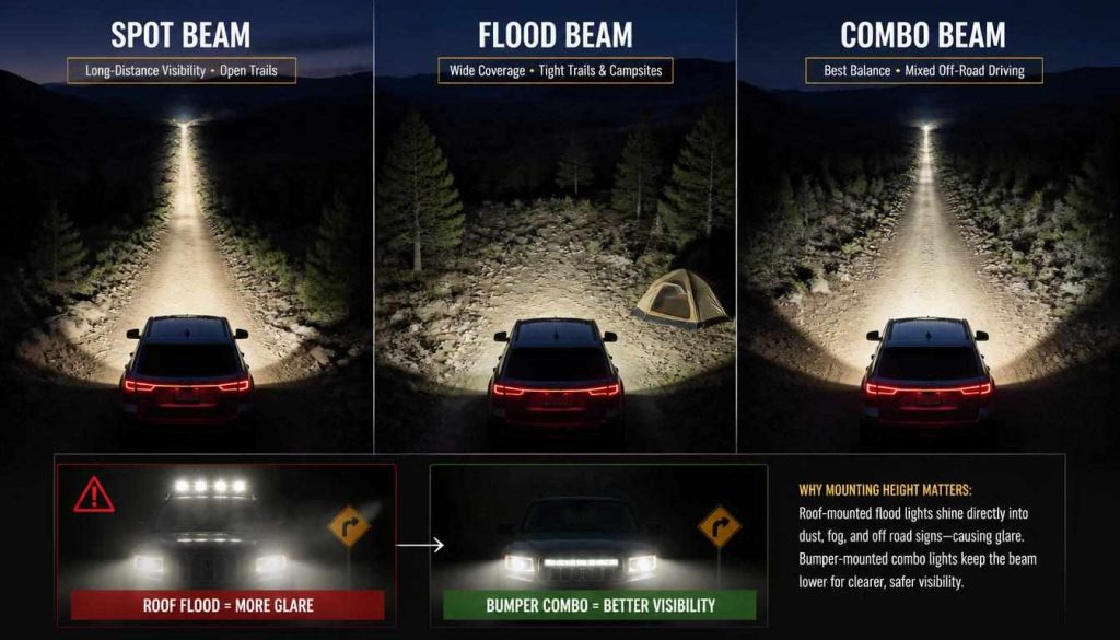
Spot beam: Concentrates light farther ahead. It is useful for open trails and long-distance visibility but provides less illumination immediately beside the vehicle.
Flood beam: Spreads light across a wider area. It is useful at lower speeds, on tight trails, around campsites, and near the sides of the Jeep.
Combo beam: Combines a concentrated center beam with wider side illumination. It is often the most practical single-bar option for mixed off-road driving.
A very wide flood beam mounted on the roof can create glare on the hood, windshield, road signs, dust, fog, or snow. A bumper-mounted combo beam usually produces less hood reflection.
Straight vs Curved Light Bars
A straight light bar normally offers:
- More universal mounting options
- Easier bracket alignment
- A concentrated forward-facing pattern
- Better compatibility with narrow grille openings
A curved light bar may offer:
- Wider side illumination
- Better alignment with a curved roof or bumper
- A more integrated appearance
However, curved bars require compatible brackets and sufficient clearance across the entire housing.
Single-Row vs Dual-Row
A single-row light bar is usually thinner and easier to hide behind a grille. It may also produce less wind noise when roof-mounted.
A dual-row bar is normally deeper and may deliver more output, but it requires more clearance and may block additional airflow. Compare effective light output and beam quality rather than judging the light only by the number of LED chips.
Check Voltage, Wattage, and Current Draw
Most automotive LED light bars are designed for 12-volt systems, but you must verify the product specification.
Estimate current draw with this formula:
Current in amps = Wattage ÷ Operating voltage
For example:
120 watts ÷ 12 volts = 10 amps
Actual current can differ when the engine is running because charging-system voltage is usually higher than 12 volts. Use the manufacturer’s rated current whenever it is available.
The wiring harness, relay, switch, fuse holder, connectors, and wire must all be rated for the complete load.
Best Mounting Locations on a Grand Cherokee
There is no single best location for every vehicle. Choose the position that provides secure attachment, useful illumination, acceptable airflow, and legal operation.
Behind the Lower Grille
A behind-grille installation offers a clean, factory-style appearance and protects the light from branches and minor impacts.
Potential disadvantages include:
- Reduced light output through grille slats
- Limited adjustment access
- Additional bumper or grille removal
- Restricted cooling airflow
- Interference with sensors or active grille components
Check that the grille will not contact the light bar when it flexes.
Lower Bumper or Hidden Bumper Mount
A hidden lower-bumper mount is popular because it keeps the light close to the road and reduces hood glare.
Vehicle-specific installations may require removal of push pins, air-dam hardware, lower trim, or bumper components. Follow the bracket manufacturer’s sequence rather than forcing plastic panels or drilling unnecessary holes.
Tow-Hook Area
The tow-hook area may provide strong factory mounting points, but the bar and brackets must not block recovery access.
Do not attach a light bracket to a lightweight decorative panel that cannot withstand vibration.
License-Plate Mount
A license-plate bracket can work for a small or medium light bar and may avoid drilling.
Check that it does not:
- Cover the plate
- Reduce radiator airflow
- vibrate excessively
- project dangerously from the bumper
- block parking sensors
Roof-Rack Mount
A roof-mounted light bar provides a high lighting position and can illuminate a wide trail area. It also creates the greatest risk of:
- Hood glare
- Wind noise
- Roof-rack vibration
- Water leaks
- Exposed wiring
- Car-wash damage
- Excess vehicle height
Position the bar far enough back or shield it so the beam does not wash across the hood. Route the wiring through a properly sealed entry point or a purpose-designed external cable channel.
A-Pillar or Ditch-Light Mount
Small LED pods mounted near the hood or A-pillars can provide side visibility without requiring one large bar.
Aim ditch lights away from the windshield and mirrors to avoid distracting reflections.
Can You Install a Light Bar Without Drilling?
A no-drill installation is possible when a compatible bracket uses existing factory bolts, tow-hook points, bumper supports, roof-rack channels, or license-plate holes.
A no-drill bracket is preferable because it:
- Reduces corrosion risk
- Avoids accidental damage behind a panel
- Makes the installation easier to reverse
- Usually provides more predictable alignment
Drilling may be necessary for a universal roof mount, custom bumper, cable gland, or fabricated bracket.
Before drilling:
- Remove or inspect the back of the panel.
- Confirm there are no wires, sensors, fluid lines, airbags, or structural components behind it.
- Mark both sides carefully.
- Drill a small pilot hole.
- Deburr the opening.
- Apply suitable corrosion protection to exposed metal.
- Install a rubber grommet or sealed cable gland where wiring passes through the hole.
Never run an electrical wire directly across a sharp metal edge.
Tools and Parts You Will Need
Essential Parts
- LED light bar
- Vehicle-compatible mounting brackets
- Mounting hardware
- Automotive wiring harness
- Relay, unless the manufacturer uses an approved internal switching design
- Inline fuse and weather-resistant fuse holder
- Dashboard switch or approved trigger interface
- Automotive-grade wire
- Ring terminals
- Crimp connectors
- Adhesive-lined heat-shrink tubing
- Split wire loom
- Rubber grommet
- Cable ties
- Dielectric grease
- Corrosion protection for drilled metal
Essential Tools
- Socket and wrench set
- Screwdrivers
- Trim-removal tools
- Wire stripper
- Quality ratcheting crimper
- Multimeter
- Test light where appropriate
- Measuring tape
- Marker
- Drill and bits, when required
- Torque wrench
- Fish tape or pull wire
- Heat gun
- Work light
- Safety glasses
- Gloves
Avoid twisting wires together and covering them with ordinary household tape. Use automotive connectors that are suitable for vibration, heat, moisture, and current load.
Safety Checks Before Installation
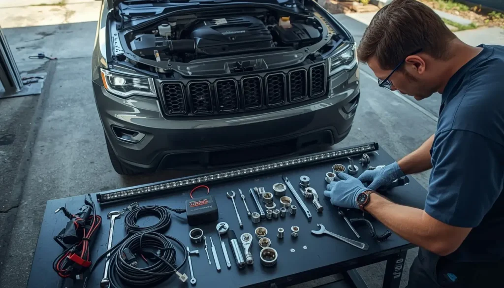
Park the Jeep on a level surface, switch off the ignition, apply the parking brake, and remove the key.
Disconnect the negative battery cable before mounting or wiring the light. Manufacturer installation guidance for auxiliary driving lights commonly requires battery disconnection, secure mounting, protected cables, and an appropriate wiring system.
Before continuing, confirm that:
- The light bar is undamaged.
- The harness is rated for the bar.
- The fuse rating matches the manufacturer’s instructions.
- The switch is designed to control a relay or low-current trigger.
- Mounting brackets are secure and correctly oriented.
- Wiring will remain clear of belts, fans, exhaust parts, steering components, pedals, and sharp edges.
- The light will not interfere with required vehicle systems.
- The planned installation is legal in your location.
Choose the Correct Wiring Method
There are several ways to control an LED light bar.
Independent Dashboard Switch
An independent switch allows the light bar to operate separately from the factory high beams.
This is convenient for off-road use, but it may allow the light to operate when public-road rules require it to switch off with low beam. It may also drain the battery if the circuit remains active when the engine is off.
Ignition-Switched Trigger
An ignition-switched trigger activates the control circuit only when the ignition or accessory circuit is on.
This reduces the chance of accidentally leaving the bar on. However, you must identify an appropriate low-current trigger without overloading the selected factory circuit.
Do not connect the main light-bar load through a small fuse tap or dashboard accessory circuit. The accessory signal should control the relay, while the light receives fused power through appropriately sized wiring.
High-Beam Trigger
A high-beam-triggered system allows the light bar to operate only when:
- The factory high beams are active
- The auxiliary-light switch is turned on
This arrangement is required in some jurisdictions for road-used driving lights.
Use the high-beam circuit only as a trigger unless the equipment manufacturer specifically provides a different approved design.
CAN-Bus or Electronic High-Beam Interface
Some modern vehicles do not provide a simple conventional high-beam wire that should be used as a trigger. A suitable interface can read the vehicle’s electronic signal and provide a controlled output for the auxiliary-light system.
Commercial CAN interfaces are designed to read signals such as high beam and parking lights without using the factory lamp circuit as the main power source.
Do not randomly probe, cut, or load communication wiring. An incorrect connection can trigger faults or damage electronic modules.
Wireless Remote or Auxiliary Switch Panel
A wireless controller or centralized accessory panel may reduce the number of wires that must pass through the firewall.
Check the controller’s:
- Maximum current per circuit
- Total current rating
- Fuse protection
- Low-voltage protection
- Waterproof rating
- Installation location
LED Light-Bar Wiring Diagram
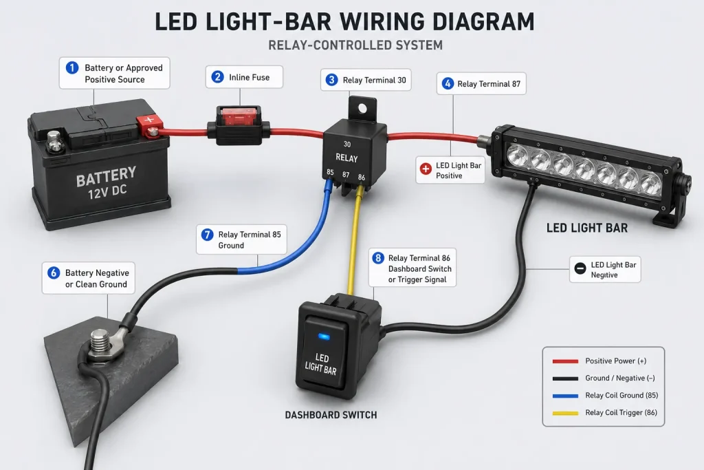
A conventional relay-controlled system normally follows this path:
Battery or Approved Positive Source
                |
            Inline Fuse
                |
          Relay Terminal 30
                |
          Relay Terminal 87
                |
       LED Light Bar Positive

LED Light Bar Negative
                |
     Battery Negative or Clean Ground

Relay Terminal 85
                |
              Ground

Relay Terminal 86
                |
   Dashboard Switch or Trigger Signal
Relay terminal numbers can vary, so verify the diagram printed on the relay.
What the Relay Does
The dashboard switch should not normally carry the full light-bar current.
Instead:
- The switch sends a small trigger current to the relay.
- The relay closes its high-current contacts.
- Fused power flows to the light bar through larger wiring.
This protects the small dashboard switch and avoids routing the full accessory load through the cabin.
Some modern lights contain internal switching and use a different connection method. Do not add or remove a relay contrary to the manufacturer’s instructions. Narva’s EX2 instructions, for example, specify internal switching for that product while also showing additional relay arrangements for certain negatively switched vehicles.
Fuse Selection
The fuse protects the wiring from excessive current. It should be installed close to the positive power connection so that as little unfused cable as possible remains exposed.
Use the fuse specified by the light or harness manufacturer. A manufacturer may pair a particular cable size with a specific fuse because the light’s current draw and internal design are known.
Never replace a repeatedly blowing fuse with a larger one before finding the cause. A blown fuse may indicate:
- Damaged insulation
- Reversed polarity
- A short circuit
- Water inside a connector
- An incorrectly wired switch
- A defective relay or light
- A harness that is too small for the load
Wire Size
Wire selection depends on:
- Current draw
- Total length of the positive and negative path
- Allowable voltage drop
- Engine-bay temperature
- Wire insulation rating
- Whether the circuit operates continuously
As a conservative starting point for short automotive runs:
| Estimated load | Starting wire size |
|---|---|
| Up to 5 amps | 18 or 16 AWG |
| 5–10 amps | 16 or 14 AWG |
| 10–15 amps | 14 or 12 AWG |
| 15–20 amps | 12 or 10 AWG |
| Above 20 amps | Use manufacturer engineering data |
Choose the heavier wire when the cable run is long or the environment is hot. The harness manufacturer’s specification takes priority over a general table.
Where to Connect Power on a Grand Cherokee
Battery and terminal locations differ by generation.
On the current Grand Cherokee, Jeep states that the main battery is under the driver’s seat, an auxiliary battery may be under the front passenger seat, and remote terminals are provided under the hood.
That does not automatically mean every under-hood post is approved as a permanent accessory connection. Check the owner’s manual for your exact vehicle and follow the accessory manufacturer’s instructions.
Positive Connection
The positive supply may come from:
- The battery positive terminal
- An approved under-hood remote terminal
- A manufacturer-approved accessory distribution point
- A dedicated fused accessory controller
Do not place an unfused cable directly on a positive terminal and route it across the engine bay.
Ground Connection
Connect the negative lead to:
- The battery negative terminal, or
- A solid manufacturer-approved chassis ground
A good chassis ground should be:
- Structurally solid
- Free from paint, corrosion, oil, and dirt at the contact point
- Tightened securely
- Protected against future corrosion
- Positioned away from excessive heat and water exposure
Do not ground the light through a thin decorative bracket unless the manufacturer specifically designed it for that purpose.
Relay and Fuse Location
Mount the relay and fuse holder:
- Near the approved positive connection
- Away from the exhaust
- Away from direct engine heat
- Away from moving components
- Away from constant water spray
- Where the fuse remains accessible
Orient a conventional relay so water cannot collect around the terminals or enter the housing.
How to Install the LED Light Bar
Step 1: Disconnect the Battery
Turn off the ignition and wait for vehicle systems to shut down.
Disconnect the negative battery terminal or follow the battery-disconnection procedure in the owner’s manual. Some modern vehicles require special steps to preserve settings or prevent electrical faults.
Prevent the disconnected terminal from accidentally touching the battery post.
Step 2: Test-Fit the Light Bar
Place the light and brackets in the intended position before drilling or removing major components.
Check:
- Overall width
- Bracket spacing
- Hood clearance
- Grille clearance
- Bumper movement
- Sensor visibility
- Cooling airflow
- Access to adjustment bolts
- Harness connector clearance
Stand in front of the Jeep and confirm that the light is centered.
Step 3: Remove Necessary Trim
Use trim tools rather than metal screwdrivers whenever possible.
Keep clips, bolts, and screws organized according to their original location. Different-looking clips may have different lengths or locking designs.
Do not pull forcefully when a panel remains attached. Look for hidden fasteners, wiring connectors, and tabs.
Step 4: Install the Mounting Brackets
Attach vehicle-specific brackets to the designated factory points.
Start all bolts by hand before tightening. This prevents cross-threading and allows minor alignment adjustments.
When using universal brackets:
- Mount them to a solid structural surface.
- Reinforce thin sheet metal when necessary.
- Confirm that the bar cannot rotate under vibration.
- Use locking hardware recommended by the manufacturer.
Step 5: Attach the Light Bar
Lift the light bar into position and install its side bolts or mounting feet.
Center the bar and tighten it enough to remain in place, but leave the angle adjustment slightly loose.
Do not fully aim the light until the wiring is complete and the Jeep is parked on a level surface.
Step 6: Mount the Relay and Fuse Holder
Choose a protected engine-bay location.
Use a proper mounting tab or bracket. Do not allow the relay and fuse holder to hang from their wires.
Keep the main fuse removed until the wiring is complete.
Step 7: Connect the Bar to the Harness
Connect the harness to the light bar, matching polarity and connector orientation.
Where a sealed plug is supplied:
- Push it together completely.
- Confirm the locking tab engages.
- Install any supplied seals.
- Do not force mismatched connectors.
Where crimp connections are required:
- Strip only the necessary insulation.
- Insert the conductor fully.
- Crimp with the correct die.
- Pull-test the connection.
- Seal it with adhesive-lined heat shrink.
Do not rely on wire colour alone. Follow the product diagram.
Step 8: Route the Wiring Through the Engine Bay
Follow an existing vehicle harness where practical, while maintaining sufficient distance from heat and moving parts.
Protect wires with split loom wherever they may rub against:
- Metal edges
- Plastic panels
- Brackets
- Engine components
- Body seams
Leave enough slack for normal engine movement, but do not leave loose loops near the cooling fan or accessory belt.
Step 9: Route the Switch Wire Through the Firewall
Look for an existing rubber grommet with enough room for the trigger wire.
Before pushing a tool through the grommet, inspect both sides. Never insert a sharp tool blindly because factory wiring may be immediately behind it.
Use fish tape or a smooth pull wire to guide the cable.
After pulling the wire through:
- Confirm the grommet remains seated.
- Seal any new opening.
- Keep the cable away from pedals.
- Keep the cable away from the steering shaft.
- Secure it under the dashboard.
Do not route the wire through a door opening where it will be pinched by weather seals.
Step 10: Install the Dashboard Switch
Choose a location that is:
- Easy for the driver to reach
- Visible at night
- Protected from accidental activation
- Clear of airbags and knee-impact zones
- Deep enough for the switch body and connector
- Easy to service later
A removable blank panel is usually preferable to drilling the main dashboard.
Before cutting, inspect the space behind the panel.
Step 11: Wire the Switch
Switch terminal arrangements differ.
A basic illuminated switch may require:
- Trigger power input
- Relay trigger output
- Ground for illumination
A five-pin switch may have separate terminals for:
- Main illumination
- Status illumination
- Trigger input
- Trigger output
- Ground
Use the diagram supplied with the switch. Do not assume two switches with the same shape use the same pin arrangement.
Step 12: Connect Power and Ground
With the fuse still removed:
- Connect the light-bar ground.
- Connect the relay ground.
- Connect the switch or trigger wiring.
- Connect the fused positive lead to the approved power point.
- Confirm all connections are insulated.
- Inspect the full cable route.
- Install the correct fuse.
- Reconnect the battery.
Keep tools away from both battery terminals while tightening a positive connection.
Step 13: Test the Light Bar
Test the system before reinstalling every trim panel.
Confirm that:
- The switch operates correctly.
- The light bar turns on.
- The light turns off when commanded.
- High-beam integration works correctly, when used.
- No warning messages appear.
- The relay does not chatter.
- The fuse does not heat excessively.
- The connectors remain cool.
- The wire does not become hot.
- The bar produces stable output without flickering.
- Factory headlights, indicators, parking sensors, cameras, and other systems continue to work.
If something is wrong, disconnect power before changing the wiring.
Step 14: Secure and Waterproof the Installation
Install loom over exposed cable and secure it at regular intervals.
Use cable ties firmly enough to hold the wire, but not so tight that they crush the insulation.
Create a drip loop where water could travel toward a connector. Position the loop below the connector so water falls away rather than entering it.
Apply corrosion protection to drilled metal and exposed mounting hardware where appropriate.
Step 15: Reinstall the Trim
Reinstall all panels, clips, splash guards, and fasteners.
Check the panel gaps and confirm that:
- No wiring is pinched.
- The harness cannot contact the exhaust.
- The bumper remains secure.
- The grille does not touch the light bar.
- All factory connectors are reattached.
Model-Specific Installation Notes
ZJ and WJ
Older Grand Cherokees may provide simpler conventional wiring and fewer front sensors, but age-related problems are more likely.
Inspect for:
- Brittle plastic clips
- Corroded fasteners
- Damaged grounds
- Previous wiring modifications
- Hardened firewall grommets
- Rust near mounting points
Do not trust an old accessory wire solely because it already exists. Verify its fuse, wire size, condition, and connection.
WK
Check the lower-grille opening, bumper construction, and available firewall access.
A universal installation may require more fabrication than a vehicle-specific bracket. Test-fit carefully before cutting the grille.
WK2
WK2 installations commonly use hidden lower-bumper or grille-mounted bars. Some vehicle-specific kits require removal of lower trim and air-dam hardware while using dedicated brackets.
Pay close attention to:
- Lower fascia clips
- Tow-hook configuration
- Parking sensors
- Adaptive cruise-control equipment
- Airflow
- Battery and terminal arrangement
- Existing firewall grommets
WL and Grand Cherokee L
Newer vehicles can have more integrated electronics and driver-assistance equipment.
Before installation, identify:
- Camera locations
- Radar locations
- Parking sensors
- Active grille systems
- Under-seat batteries
- Under-hood remote terminals
- Digitally controlled lighting
- Hybrid or high-voltage components, when equipped
Do not work on orange high-voltage cables or components. An accessory light bar should remain within the conventional low-voltage accessory system.
How to Test the Wiring With a Multimeter
A multimeter can identify whether the problem is at the power source, fuse, relay, trigger, ground, or light bar.
Test Supply Voltage
Set the meter to DC voltage and measure across the approved positive and negative points.
A severely low reading may indicate a discharged battery or poor connection.
Test Both Sides of the Fuse
With the circuit commanded on, measure voltage at both fuse terminals.
Voltage on one side but not the other indicates an open fuse or poor fuse-holder contact.
Test Relay Terminal 30
Terminal 30 should normally receive fused battery power.
No voltage at terminal 30 points to a power-supply, fuse, or wiring problem.
Test the Trigger Terminal
Operate the dashboard switch or high beams and check the relay trigger terminal.
If the trigger appears but the relay does not click, the relay ground or relay itself may be faulty.
Test Relay Output
When the relay is activated, terminal 87 should provide power to the light bar in a standard normally open arrangement.
Voltage at terminal 30 but not terminal 87 can indicate a defective relay or incorrect terminal identification.
Check the Ground
A ground can look clean and still create resistance.
Measure voltage between the light-bar negative terminal and battery negative while the bar is operating. A noticeable voltage reading indicates loss in the ground path.
Clean, tighten, or relocate the ground connection as necessary.
How to Aim the LED Light Bar
Aim the light after the Jeep is fully assembled.
- Park on level ground.
- Set the tire pressures correctly.
- Remove unusually heavy temporary cargo.
- Position the Jeep facing a wall or garage door.
- Mark the approximate center height of the light.
- Switch on the bar.
- Adjust the beam below the level that would shine directly into another driver’s eyes.
- Check hood and windshield reflections.
- Tighten the adjustment bolts evenly.
- Test the beam in a safe off-road area.
A roof-mounted bar may need to be aimed farther ahead to prevent the hood from being flooded with light. A bumper-mounted flood beam should not be aimed so low that it creates an overly bright foreground and reduces distance vision.
Do not aim the bar solely for maximum brightness. A controlled beam is more useful than uncontrolled glare.
Common Installation Problems
The Light Bar Does Not Turn On
Possible causes include:
- Missing or blown fuse
- Poor battery connection
- Poor ground
- Incorrect relay terminals
- Faulty switch
- Missing trigger signal
- Reversed connector
- Defective light bar
Test the circuit in stages rather than replacing parts randomly.
The Light Bar Flickers
Common causes include:
- Loose ground
- Loose crimp
- Poor fuse-holder contact
- Relay chatter
- Insufficient trigger voltage
- Incorrect high-beam connection
- CAN-bus incompatibility
- Undersized wiring
If flickering begins only when connected to the high beams, verify whether the vehicle requires a compatible trigger interface.
The Fuse Keeps Blowing
Immediately stop replacing fuses.
Inspect for:
- Pinched wires
- Melted insulation
- Reversed polarity
- A shorted connector
- Water intrusion
- Incorrect relay wiring
- A fuse below the manufacturer’s required rating
- A light or harness drawing excessive current
Never install a larger fuse without confirming the wire and equipment can safely support it.
The Switch Lights Up but the Bar Does Not
The switch illumination circuit may be working while the relay trigger or main power circuit is not.
Test:
- Switch output
- Relay click
- Terminal 30 power
- Terminal 87 output
- Light-bar ground
- Light connector voltage
The Bar Works but the Switch Does Not Illuminate
The switch’s illumination ground or lighting terminal may be missing.
Check the switch-specific diagram because some switches use separate terminals for backlighting and “on” indication.
The Light Bar Stays On
Possible causes include:
- Trigger wire connected to constant power
- Switch terminals reversed
- Relay contacts stuck closed
- Incorrect high-beam trigger
- Backfeeding through an illuminated switch
- Incorrect accessory-panel programming
Disconnect the fuse until the fault is corrected.
The Battery Drains Overnight
Check whether:
- The light bar can remain on with the ignition off.
- The switch illumination remains powered.
- A wireless controller stays awake.
- The relay remains energized.
- The accessory panel has excessive standby current.
- The light was accidentally left on.
Consider an ignition-controlled trigger or low-voltage cutoff.
The Radio Develops Interference
Electrical noise may come from a low-quality LED driver, poor ground, long unshielded wiring, or cable routing near an antenna or audio harness.
Improve the ground, separate the wiring routes, and use manufacturer-approved suppression components when required.
Moisture Appears Inside the Light Bar
Temporary condensation and water intrusion are not always the same issue.
Inspect:
- Lens seals
- Cable entry
- Connector seals
- Housing damage
- Drain or breather design
- Mounting orientation
Do not permanently seal a designed breather opening.
A Dashboard Warning Appears
Disconnect the accessory and restore the factory circuit before continuing.
A warning may indicate:
- The wrong factory wire was tapped.
- A monitored lighting circuit was loaded.
- The high-beam signal is electronically controlled.
- A module or connector was disturbed.
- The installation interferes with a sensor.
Use a suitable interface or obtain professional diagnosis.
Waterproofing and Maintenance
Inspect the installation after the first drive and again after the first off-road trip.
Check:
- Mounting-bolt tightness
- Bracket movement
- Wire chafing
- Loose cable ties
- Connector seals
- Fuse-holder condition
- Corrosion
- Water entry
- Beam alignment
In regions where roads are treated with salt, clean the brackets and connectors regularly.
Do not pressure-wash directly into electrical connectors, relay housings, cable glands, or light-bar breathers.
Is an LED Light Bar Legal on Public Roads?
Rules differ between countries and may also differ by state, province, territory, or local jurisdiction. Treat a bar advertised as “off-road only” as unsuitable for public-road use unless local law clearly permits it.
United States
Federal requirements prohibit additional equipment from impairing the effectiveness of required vehicle lighting, while the use of supplemental aftermarket lighting is also affected by state law. NHTSA specifically notes that state laws can vary.
Check your state’s requirements for:
- Lamp approval
- Mounting height
- Number of auxiliary lights
- Permitted colours
- Covers
- High-beam switching
- Public-road use
United Kingdom
Vehicle lamps are governed by the Road Vehicles Lighting Regulations. Colour, position, security, operation, and the risk of dazzling other road users are important considerations.
Do not use decorative, flashing, or coloured lighting that could be confused with emergency or required vehicle lighting.
Canada
Canadian rules combine federal vehicle standards with provincial or territorial requirements.
For example, British Columbia specifies conditions for auxiliary driving lamps, including permitted number, mounting position, and white-light output. Other provinces may use different requirements.
Check the rules where the vehicle is registered and operated.
Australia
Australian requirements involve national design rules and state or territory regulations.
South Australian guidance, for example, requires additional driving lights to be fitted according to applicable standards and to extinguish automatically when low beam is selected. Requirements can differ elsewhere in Australia.
Before using the bar on a public road, confirm:
- Permitted mounting position
- Allowed number of lights
- High-beam switching requirements
- Approved lamp markings
- Beam colour
- Glare restrictions
- Cover requirements when not in use
Frequently Asked Questions About How to Install an LED Light Bar on a Jeep Grand Cherokee
What size LED light bar fits a Jeep Grand Cherokee?
The correct size depends on the available opening and mounting position. Measure the total available width and compare it with the light’s complete housing width and bracket spacing. A nominal 20-inch bar may require more than 20 inches of overall clearance.
Can I install a light bar behind the grille?
Yes, when sufficient space, airflow, bracket strength, and sensor clearance are available. Grille slats can reduce output, so test the beam before completing the installation.
Do I need a relay?
Most conventional high-current light-bar installations should use a relay or an appropriately rated electronic accessory controller. Some lights contain manufacturer-designed internal switching and require a different connection method. Follow the product instructions.
Can I wire the light bar directly to the battery?
The main power source may connect to the battery or an approved remote terminal, but the circuit must be fused close to that connection. Do not run an unfused positive wire through the vehicle.
Where should I run the switch wire through the firewall?
Use an existing protected rubber grommet where possible. Verify the location from both sides before inserting a pull wire. Exact access differs by generation and trim.
Can I install a light bar without drilling?
Yes, when a vehicle-specific bracket uses existing factory mounting points. A no-drill installation is usually easier to reverse and avoids creating new corrosion points.
What fuse size should I use?
Use the fuse specified by the light-bar or harness manufacturer. The correct fuse depends on normal current draw, wire capacity, and product design.
What wire gauge is best?
Wire size depends on current draw and total circuit length. Longer runs and higher loads require heavier wire. Use the harness manufacturer’s specification whenever available.
Can a light bar drain the battery?
Yes. A light bar can discharge the battery when used with the engine off or accidentally left on. An ignition-switched trigger or low-voltage cutoff can reduce this risk.
Can the light bar turn on with the high beams?
Yes. A relay, suitable high-beam trigger, and dashboard isolation switch can allow the bar to operate with the factory high beams. Newer electronically controlled lighting may require a compatible interface.
Will a light bar interfere with adaptive cruise control?
It can if the bar or bracket blocks the radar, camera, sensor field, or required airflow. Identify all front sensors before selecting the mounting position.
Is a roof-mounted or bumper-mounted bar better?
A bumper-mounted bar normally creates less hood glare and wind noise. A roof-mounted bar can provide a higher and wider field of light but requires more careful aiming and weatherproof cable routing.
Will an LED light bar damage the alternator?
A properly sized light bar should not damage a healthy charging system when its total electrical load remains within the vehicle’s available capacity. High-output or multiple-light installations should be evaluated based on combined current draw and charging-system reserve.
Can I use two light bars on one relay?
Only when the combined current remains within the relay, fuse, connector, and wire ratings. Use separate circuits when the total load approaches the limit or independent control is required.
Why does my light bar flicker?
Flickering is commonly caused by a poor ground, loose connector, unstable trigger, relay chatter, undersized wiring, or an incompatible high-beam connection.
How long does installation take?
A simple bolt-on installation may take two to four hours. Custom fabrication, bumper removal, roof drilling, or complex electronic integration can take considerably longer.
Final Installation Checklist
Before driving, confirm that:
- The light bar and brackets fit the exact model.
- The mounting surface is structurally solid.
- Every bolt is secure.
- The bar does not block airflow.
- The bar does not block a camera, radar, or parking sensor.
- Recovery points remain accessible.
- The positive circuit is fused near its power source.
- The fuse has the correct rating.
- The relay or controller is correctly rated.
- The ground connection is clean and secure.
- Wires are protected with loom.
- No cable touches a sharp edge.
- No cable is near the exhaust, fan, belt, or steering parts.
- The firewall opening is sealed.
- The switch is mounted safely.
- The light turns off correctly.
- No warning message appears.
- Factory lighting and safety systems still work.
- The beam is aimed without dangerous glare.
- The installation complies with local law.
Conclusion
Installing an LED light bar on a Jeep Grand Cherokee is manageable when you treat the mounting and electrical work as one complete system.
Begin by confirming your Jeep’s exact generation, trim, mounting space, battery arrangement, and front-sensor locations. Use a vehicle-specific no-drill bracket where possible, power the bar through a correctly fused harness, protect every wire from heat and abrasion, and test the circuit before reinstalling the trim.
The most common installation mistakes are choosing an incompatible bracket, running the full load through a small switch, using an incorrect fuse, making a weak ground connection, blocking front sensors, and tapping an unsuitable high-beam wire.
Take time to test, weatherproof, and aim the light correctly. When the vehicle uses complex electronic lighting or you cannot positively identify the correct trigger and power connections, have the final wiring completed by a qualified automotive electrician.
“Cars aren’t just machines. They’re freedom, memory, and a little bit of grease under your fingernails.”
I’m Theodore Roosevelt—though my friends just call me “Ted” (and no, I’m not related to the president, though I do share his love for adventure). I grew up in Detroit in the 1970s, back when the city was still the heart of the American auto industry. My first love was a rusted-out 1967 Mustang my father and I rebuilt in our garage when I was fifteen. That project taught me that cars have souls. After spending twenty years as a mechanic and another ten writing for magazines, I started this blog to help everyday drivers and weekend wrenchers feel confident under the hood. Whether you’re restoring a classic or just trying to keep your daily driver alive for one more winter, I’m here to help you get there.