
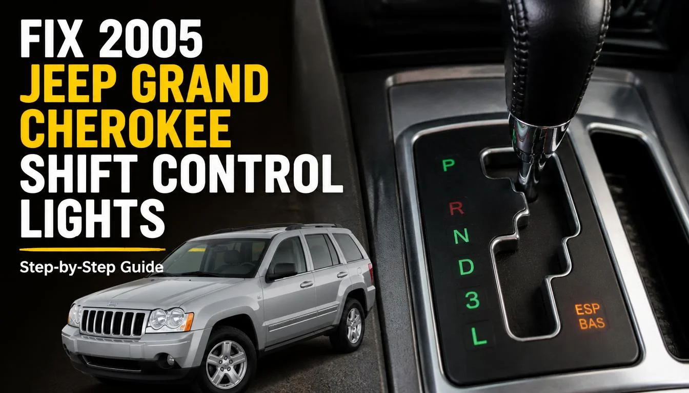
How To Repair 2005 Jeep Grand Cherokee Shift Control Lights usually comes down to three things: replacing a blown fuse, cleaning a corroded ground point, or swapping a bad bulb socket. Most owners chase the wrong part because they skip the simplest checks first. Check your interior fuse panel and under-hood junction box for a blown 10A or 15A fuse feeding the instrument cluster.
If that fuse is fine, track down the main ground strap near the driver’s side kick panel and clean it until bare metal shows. Only after ruling those two items out should you pull the instrument cluster and test individual bulb filaments.
When those three steps don’t bring the lights back, the real culprit is usually the Transmission Range Sensor sending no signal to the cluster or a cracked solder joint on the instrument panel circuit board. The diagnostic path changes completely depending on whether zero lights work or just some of them. Following the right test branch first saves you hours of guesswork and a trip to the auto parts store for parts you won’t need.
Let’s figure out which branch applies to your situation.
The 3-Minute Decision: Which Branch Should You Test First?
Before you reach for a multimeter or start unscrewing anything, you need to pin down exactly what symptom pattern you’re dealing with. The repair path diverges sharply depending on whether all the gear indicator lights are dead, only a few are out, or they flicker and dim unpredictably. Getting this diagnosis right in the first three minutes determines whether you end up swapping a ten-dollar fuse or rebuilding a circuit board.
The quickest way to sort this out is to sit in the driver’s seat with the key turned to the ON position, engine off, and watch what the instrument cluster actually does. If every single gear position light stays completely dark regardless of where you move the shifter, you’re dealing with a power or ground problem in Branch A. This means the cluster itself isn’t receiving electricity, and no amount of bulb replacement will fix it.
Think of it like trying to light candles in a room with no wiring. The bulbs are fine, but nothing will glow until you restore power to the whole system.
If some lights work while others stay dark, you’re firmly in Branch B territory. This is a localized issue. A burned-out filament in one bulb, a corroded socket contact, or a broken trace on the cluster board serves only those specific positions.
The good news here is that your cluster has power. The bad news is that you’ll need to pull the instrument panel assembly and do some hands-on testing with a multimeter to find the dead connection. Pulling the cluster on a 2005 Grand Cherokee takes about fifteen minutes if you take your time and keep the tiny retaining clips organized.
The third scenario lands in Branch C and involves dim or inconsistent illumination that changes when you tap the dashboard or adjust the dimmer knob. Flickering lights that respond to body movement almost always point to a poor ground connection somewhere between the instrument cluster and the vehicle chassis. The 2005 WK generation is especially prone to this because the main body ground straps run through areas that collect road salt and moisture.
If your headlights are on and the shift lights go noticeably dimmer when you turn the steering wheel left or right, grab a rag and a wire brush. You’ve got a ground to clean.
| Symptom Pattern | Diagnostic Branch | Likely Root Cause | First Action |
|---|---|---|---|
| All lights completely dead | Branch A | Blown fuse or open ground | Check interior fuse panel |
| Some lights work, others dead | Branch B | Bad bulb or socket contact | Pull cluster and test filaments |
| Lights flicker when moving | Branch C | Loose ground or worn connector | Inspect and clean ground points |
| All lights dim at night | Branch C variant | Faulty dimmer switch | Test dimmer switch output voltage |
| Lights come on randomly | Unknown | Wiring short or PCM issue | Scan for codes and inspect harness |
One thing most owners miss is the connection between shift indicator problems and other dashboard warnings. If you’re seeing strange behavior across multiple gauge clusters or warning lights, check common dashboard warning light patterns for broader troubleshooting context. The instrument cluster shares power feeds and ground paths with other systems, so a single bad ground can create cascading issues that look unrelated at first glance.
Here’s the practical test you should run before touching anything else. Move the gear selector through every position slowly while watching the indicator lights. Do all six positions light up correctly when the headlights are off?
Now flip on your parking lights or headlights. Do the same lights illuminate at reduced brightness through the dimmer circuit? If the answer to either question is no, or if you notice the lights jumping around erratically, you now have enough information to pick your branch and stop wasting time on dead-end repairs.
Jumping straight to buying a new Transmission Range Sensor because your Reverse light won’t come on is a classic mistake. That sensor costs between $80 and $200 depending on whether you go OEM or aftermarket, and it could be entirely healthy while a two-dollar fuse sits blown in your under-hood junction box. Take the three minutes to confirm your symptom pattern first.
Then follow the corresponding branch below for the exact steps that match your situation.
How the Shift Position Indicator System Actually Works
Understanding how this system communicates between the transmission, the sensors, and your dashboard makes troubleshooting infinitely faster than guesswork. The 2005 Jeep Grand Cherokee uses a straightforward electrical architecture that Mopar designed for reliability, but age and environment wear it down in predictable ways. When you know the signal path from start to finish, you can isolate faults with a multimeter instead of swapping parts and hoping something sticks.
The Role of the Transmission Range Sensor (TRS/PNP Switch)
The Transmission Range Sensor, also called the Park/Neutral Position switch, is the brain of this whole operation. It mounts directly to the transmission case and reads the physical position of the gear selector linkage. Every time you move the shifter from Park to Drive or reverse, the TRS sends a unique voltage signal on specific circuits to the Powertrain Control Module and the instrument cluster.
The PCM uses this data to control starting, shift timing, and torque management. The cluster uses it to light up the correct gear position indicator on your dash.
The TRS on the WK Grand Cherokee typically outputs a reference voltage around 5 volts from the PCM, then varies the signal voltage depending on which gear you select. Park and Neutral usually share similar signal characteristics because the transmission is mechanically locked in those positions. Reverse sends a different voltage signature that also triggers the backup light circuit simultaneously.
Drive, Second, and First each carry their own distinct voltage ranges that the instrument cluster interprets and maps to the corresponding illuminated letter on the gauge face.
When this sensor fails, you often see more than just missing shift lights. You might notice harsh or delayed shifts, the vehicle refusing to start because the PCM doesn’t detect Park, or even a Check Engine light with codes like P0705, P0706, or P0707. These codes specifically reference the TRS circuit malfunctioning, sending inconsistent voltage, or reporting a mechanical failure inside the switch itself.
If you’re reading any of these codes alongside your lighting problem, review related transmission diagnostic approaches for additional context on how sensor failures compound across systems.
The connector at the back of the TRS is a known weak point. Water intrusion from washing the engine bay or driving through deep puddles seeps into that multi-pin connector over time. Corrosion builds on the pins, resistance increases, and the signal becomes intermittent.
Sometimes tapping the connector temporarily restores function, which is your clue that cleaning or replacing that plug solves the problem without needing a full sensor swap.
Power, Ground, and Signal Path to the Instrument Panel Cluster
The instrument cluster receives power through multiple fused circuits in the under-hood Junction Case, also called the power distribution center. The primary feed for gauge illumination and indicator lights typically runs through a 10-amp or 15-amp fuse labeled IPC or INSTR in the fuse diagram. This fuse sits in the under-hood box on the driver’s side firewall, not the interior panel behind the pull-out cover on the left side of the dashboard.
Confusing these two locations is the number one reason people walk away from their fuse check thinking everything is fine when they actually checked the wrong panel entirely.
Once power arrives at the cluster connector, it passes through the dimmer switch circuit before reaching the bulb sockets. The dimmer switch is essentially a variable resistor that drops voltage when you turn your headlights on. At full brightness with headlights off, the cluster gets nearly full battery voltage.
Turn the dimmer knob and the resistance increases, dropping the voltage to create that softer nighttime illumination. When the dimmer circuit fails or a wire breaks inside the steering column harness, you lose all backlighting even though the bulbs themselves and their individual power feeds remain intact.
The ground path is equally critical and just as frequently overlooked. The instrument cluster grounds through a chassis connection point located behind the driver’s side dashboard, routing through the firewall and down to the vehicle frame. This ground point, often designated as G-series in factory wiring diagrams, accumulates dirt, rust, and paint overspray over the years.
A high-resistance ground causes exactly the same symptoms as a lost power feed. The cluster may flicker, dim randomly, or refuse to illuminate any lights at all. Cleaning this ground point with a wire brush until you see shiny metal is a twenty-second fix that solves mysterious electrical gremlins half the time.
Signal wires carrying TRS data enter the cluster through separate pins on the main harness connector. The cluster contains a small driver circuit that translates these voltage signals into ground paths for individual bulbs. When the PCM reports Reverse via the TRS signal wire, the cluster internally grounds the Reverse bulb circuit, completing the loop and lighting that position.
If the cluster’s internal driver chip fails, you could have perfect power and ground but still see no illumination for specific gears. This internal failure is less common than external wiring issues but absolutely possible on twenty-year-old electronics.
How the Dimmer Switch Controls Backlight Brightness
The headlight dimmer switch lives in the instrument cluster housing itself on the 2005 Grand Cherokee. It’s a rotary potentiometer that the driver turns to adjust gauge and indicator brightness. When you rotate the dial, you change the resistance in the cluster illumination circuit.
Lower resistance means brighter lights. Higher resistance dims everything down for nighttime driving. This elegant analog design has been used in vehicles for decades and rarely fails catastrophically.
However, the potentiometer wiper track inside the dimmer switch accumulates carbon dust and conductivity loss over tens of thousands of rotations. When it gets dirty or worn, you get dead spots in the rotation range. Turn the dimmer to a certain angle and all your cluster lights cut out completely.
Turn it back slightly and they return. This intermittent behavior mimics a wiring problem and sends people chasing harnesses when the real fix is replacing the dimmer switch assembly or cleaning the existing unit with electrical contact cleaner.
Some owners bypass this entire system by installing aftermarket LED conversion kits or wiring directly to constant power. This eliminates the dimming feature entirely, giving you full-brightness shift lights at all times. While this works electrically, it creates glare at night and defeats the original design intent.
The factory dimming circuit exists for a reason. Blinding your peripheral vision while driving at night is dangerous and unnecessary when the system works properly.
If you want to explore more dashboard and lighting adjustment topics, this guide on dash light dimmer adjustments covers similar principles that apply across Jeep platforms and can help you troubleshoot related brightness issues. The underlying electrical concepts remain consistent even though specific connector shapes and fuse locations differ between models.
Branch A: No Lights At All — Start With These Two Checks
When every single gear position indicator stays dark, you’re looking at a systemic electrical failure rather than an individual component problem. Your cluster has lost either power, ground, or both, and until you restore one of those foundations, no amount of bulb hunting will help. This is actually the easiest branch to diagnose because the problem space is narrow and the tests are straightforward.
Step 1: Verify the Right Fuses Are Actually Alive
Start at the under-hood Junction Case on the driver’s side firewall. Pop the plastic cover and consult the fuse diagram printed on the inside surface. Look for fuses labeled IPC, INSTR, or GAUGE.
Terminology varies slightly between Mopar documentation years but all refer to the same instrument cluster power feed. On the 2005 Grand Cherokee, this is typically a 10-amp or 15-amp blade-type fuse. Remove it carefully with the plastic fuse puller tool that came with the vehicle, or use a pair of needle-nose pliers if you don’t have the original tool handy.
Visual inspection alone isn’t enough. The thin metal strip inside a blown fuse can sometimes stay partially connected, giving a false impression that the fuse is good. Pull out a multimeter, set it to continuity mode, and touch one probe to each metal tab on the fuse.
A solid beep means the fuse is alive. No beep means it’s blown and needs replacement. Always replace with the exact amperage rating shown on the fuse diagram.
Putting in a 20-amp fuse because you couldn’t find a 15-amp is a fire hazard waiting to melt your wiring harness.
Check the interior fuse panel next, located behind the small rectangular cover on the lower left side of the dashboard near the driver’s knee. Pull that cover off and inspect the fuses labeled RADIO, IGNITION, or CLUSTER. These provide secondary power feeds and accessory circuits that feed into the instrument panel.
A blown radio fuse won’t kill your shift lights directly, but a failed ignition-fed cluster supply will. The 2005 WK shares several fuse circuits between the radio and cluster due to how Chrysler grouped accessory loads, so check both sections thoroughly.
If your multimeter shows no continuity on the IPC fuse, replace it with the exact same amperage rating. Then turn the key to ON and check whether the shift lights illuminate. If they do, you found your problem and the fuse blew for a reason, likely a short in the wiring downstream. Investigate that short before installing another fuse, or you'll blow the replacement immediately. If the new fuse blows again within seconds, you have a hard short to ground somewhere in the cluster harness and need to trace it with a wiring diagram.
Step 2: Clean and Tighten the Main Cluster Ground Points
If your fuses check out and you still have zero illumination, ground is your prime suspect. The instrument cluster grounds through multiple points, and any single open ground will kill the entire assembly. The primary ground for the dashboard electronics routes through a chassis connection behind the driver’s side kick panel, fastened to the inner fender apron.
This location sits low in the engine bay valley where road spray, salt, and standing water accumulate year after year. Corrosion builds up on the grounding surface faster than anywhere else in the vehicle.
Locate the ground strap by tracing the black insulated wire coming from the instrument cluster harness back toward the firewall. It terminates at a bolt securing a ring terminal to a painted metal surface. That bolt holds multiple grounds together, so you’re not just dealing with one circuit.
Clean the ring terminal with sandpaper or a wire brush until the metal shines. Clean the contact surface on the chassis frame beneath it the same way. Paint, rust, and dirt are electrical insulators.
Any layer between the ground strap and bare steel creates resistance that starves your cluster of a proper return path.
Reattach the ground bolt and tighten it securely. A loose ground creates the same symptoms as a missing one, so make sure that connection is snug. After reconnecting, turn the key to ON and observe your shift lights.
If illumination returns immediately, you’ve solved the problem with ten minutes of brushing and tightening. If the lights remain dead, move on to checking the secondary ground path at the transmission range sensor connector and the main engine-to-chassis ground strap beneath the vehicle.
When Branch A Leads to a Bad Dimmer Switch or Worn Connector
Sometimes your fuses are good, your grounds are clean, and you still have no lights. In this scenario, the failure has migrated upstream to the dimmer switch itself or the main connector harness at the back of the instrument cluster. The plastic connector housing deforms over time from heat cycling, and the metal terminal pins inside spread apart until they lose contact with the mating tabs on the cluster.
Wiggle the connector while the key is on and watch for intermittent flash. Even a brief moment of illumination while you move the harness tells you everything you need to know.
The dimmer switch within the cluster can also fail internally. If you measure voltage at the cluster connector pin that feeds the dimmed illumination circuit and find zero volts despite having confirmed power at the fuse, the dimmer switch has opened its internal circuit. Replacement requires removing the cluster bezel, extracting the gauge assembly, and desoldering or unplugging the dimmer module depending on the manufacturing variant.
Some cluster rebuilders include dimmer switch replacement in their service packages, which is worth considering if you’re already pulling the unit.
A worn TRS connector at the transmission also deserves mention here. If the sensor sends no signal because its connector pins are corroded, the cluster receives no gear position data and may default to illuminating nothing rather than guessing. This produces the same all lights dead symptom but originates at the transmission, not the dash.
Scan for P0705 through P0707 codes with an OBD-II reader to distinguish this case from true power loss. Codes pointing to the TRS circuit confirm the sensor path is broken upstream of the cluster.
Branch B: Some Lights Out or Flickering — Focus on Bulbs and Contacts
When you’ve confirmed that the cluster has power and a good ground but certain gear positions simply refuse to light up, you’re working with a localized fault. Only the affected positions are problematic. Park and Neutral glow fine but Drive stays dark.
Reverse works intermittently. Second and First flicker when you tap the shifter. Each of these patterns points to a very different root cause within the cluster assembly or the wiring harness between the TRS and the instrument panel.
Pulling the Cluster: What You Need to Remove and Where
Removing the instrument cluster on the 2005 Grand Cherokee requires patience more than skill. Start by disconnecting the negative battery terminal and waiting at least two minutes for the airbag system capacitors to discharge. The cluster sits behind a decorative bezel secured by two Torx screws hidden behind plastic caps on the upper left and right corners.
Pry those caps off gently with a flathead screwdriver wrapped in tape to prevent scratch marks. Remove the Torx screws and set them somewhere safe. They’re small and roll away quickly.
Gently pull the cluster forward from the dashboard. It's connected by three electrical harnesses on the rear: a large main connector, a smaller connector for additional lamp circuits, and occasionally a third for optional features depending on your trim level. Support the cluster with both hands as you slide it free. Disconnect each harness by pressing the locking tab and pulling straight back. Do not yank on the wires themselves. Label each connector or photograph the layout before disconnecting so you can reassemble everything in the correct order later.
With the cluster removed and resting on a soft towel on your workbench, you can see the back of the circuit board and all the bulb socket assemblies. The shift position indicators use standard wedge-base bulbs, typically 194 or 168 type, rated at around 1.4 watts each. These are the same small bulbs used in dome lights, license plate lights, and various interior illumination applications throughout your Jeep.
You can grab replacements at any auto parts store for a few dollars per bulb.
Testing Bulb Filaments vs. Checking Socket Contact Resistance
Set your multimeter to the ohms setting and test each shift indicator bulb individually. Touch one probe to the threaded metal base and the other to the tip contact at the bottom. A good bulb reads between 2 and 10 ohms depending on wattage.
An open circuit reads infinity or OL on your meter, confirming the filament has broken. Don’t trust a visual inspection alone. Micro-fractures in the filament are invisible to the naked eye but enough to keep the bulb from lighting.
Next, check the bulb sockets themselves. Insert a multimeter probe into the center contact point of each socket and touch the other probe to the threaded sleeve. You should read near-zero resistance, indicating a clean conductive path.
High resistance here means the spring contact inside the socket has collapsed or corroded. These springs lose tension over time from thermal expansion and contraction cycles. A weak spring creates poor electrical contact even with a perfectly good bulb installed, producing dim or nonexistent illumination.
If you find a socket with elevated resistance, you have three options. First, carefully spread the center spring contact outward with a small pick or needle-nose pliers to restore tension. This temporary fix works well if you're in a pinch. Second, replace the individual socket assembly if you can source the part separately. Third, replace the entire cluster board if multiple sockets are degraded, which is common on twenty-year-old vehicles where every socket has experienced the same thermal fatigue.
The Hidden Culprit: Cracked IPC Solder Joints and Tin Whiskers
This is the part most DIYers never consider, and it’s responsible for a surprising number of seemingly random instrument cluster failures on WK Generation Jeeps. The circuit board inside your cluster has thousands of solder joints connecting components together. Over two decades of heat cycling, warming up during driving and cooling down after shutdown, those solder joints expand and contract microscopically.
Eventually, hairline cracks form in the solder, creating what technicians call cold solder joints.
A cracked solder joint on the trace that serves your Reverse light creates exactly the symptom you’re experiencing. Perfect function for all other positions, complete darkness for one specific gear. Tap the cluster board gently with a wooden handle while someone watches the dash, and you might see the light flicker on momentarily.
That momentary illumination confirms a cracked trace that needs reflowing with a soldering iron.
Tin whiskers add another layer of complexity. These are microscopic strands of pure tin that grow spontaneously from lead-free solder joints, particularly on boards manufactured in the mid-2000s when the automotive industry shifted away from leaded solder. A single tin whisker can bridge adjacent traces on the circuit board, creating a short circuit that kills multiple indicators or causes erratic behavior.
Finding and trimming these whiskers under magnification is delicate work best suited for a professional cluster rebuilder unless you have experience with SMD rework.
If you’re comfortable with a soldering iron and a magnifying lens, you can inspect every joint on the cluster board under good light, touch up any that look dull or cracked, and trim visible whiskers with fine tweezers. This restoration technique can revive a cluster that parts stores would otherwise classify as beyond repair. For those uncomfortable with soldering work, several reputable instrument cluster rebuild services specialize in this exact type of microscopic circuit board repair and typically charge between $150 and $300, far less than a brand-new replacement cluster.
Branch C: Dim or Inconsistent Illumination — Follow the Voltage Drop
Flickering lights that respond to bumps, vibrations, or dimmer knob adjustments tell a very different story from complete darkness or isolated dead positions. This symptom pattern points directly to resistance issues in the power or ground paths, places where current struggles to flow freely and voltage drops fluctuate under load. The cluster sees variable voltage at its terminals, which makes every light on the panel brighten and dim together rather than affecting individual positions.
Dimmer Switch Output Testing with a Multimeter
Set your multimeter to DC voltage mode and connect the red probe to the illumination feed pin on the cluster connector. Consult a wiring diagram to identify the correct pin number for your specific cluster variant. Connect the black probe to a known good ground point on the dashboard metal.
Turn the key to ON and note the voltage reading. With the dimmer knob at maximum brightness, you should see approximately 12 to 12.6 volts. Rotate the dimmer knob slowly and watch the voltage decrease smoothly.
Any sudden drops to zero or erratic bouncing indicates a failing potentiometer inside the switch.
If the voltage drops to zero at any point during rotation, the dimmer switch has a dead spot caused by worn contact tracks. Spraying electrical contact cleaner into the switch mechanism while rotating the knob can sometimes clear the deposit and restore function temporarily. However, this is almost always a temporary fix. The underlying wear on the resistive track continues, and the dead spot will return within weeks or months. Plan to replace the dimmer switch assembly or the entire cluster if you want a permanent solution.
Testing the dimmer switch this way isolates the problem from everything else in the system. If voltage drops normally through the full rotation range, your dimmer is healthy and the flickering originates elsewhere, likely in the ground path or at a connector junction. If voltage behaves erratically, you’ve found your culprit and can order the replacement part with confidence.
Identifying High-Resistance Ground Paths Across the Dash
Voltage drop testing on the ground side reveals problems that continuity testing misses. Connect your multimeter in voltage mode across the ground path. Red probe to the cluster ground pin, black probe to the chassis ground point beneath it.
Turn the key on and observe the reading. A healthy ground path shows less than 0.1 volts drop. Anything above 0.5 volts indicates excessive resistance in the ground connection that starves your cluster of proper return current.
This high resistance typically comes from three sources. First, corroded ground straps running from the dashboard framework to the vehicle chassis. These braided copper straps sit low in the engine bay and absorb road salt spray constantly.
Second, paint or primer covering the ground contact point on the frame where the strap bolts down. Factory painters sometimes miss these spots during assembly, leaving a thin insulating layer that degrades further over time. Third, loose or oxidized bolt connections at the ground distribution points throughout the vehicle.
Cleaning ground paths requires getting to bare metal. Use a wire brush, sandpaper, or a grinding wheel to remove all paint, rust, and corrosion from the contact surfaces. Reassemble with the bolt tightened to specification.
Overtightening strips threads on aluminum chassis members. Undertightening allows vibration to loosen the connection over time. Apply dielectric grease to the cleaned surfaces before reassembly to slow future corrosion.
This maintenance step should be part of any thorough electrical diagnosis.
Moisture Intrusion and Corrosion at Connector Pins
Water entering the instrument cluster from a leaking windshield deflector channel or damaged weatherstripping is a slow-moving disaster. Moisture condenses inside the cluster housing, deposits minerals on the circuit board traces, and creates gradual short circuits between adjacent pathways. The effects appear gradually at first.
Lights that work after a cold start but fail once the cluster warms up. Thermal expansion closes gaps in the corrosion layer temporarily, restoring function until the next drive cycle cycles the problem again.
Inspect every connector in the cluster harness for green or white corrosion deposits on the metal pins. Pull the connectors apart carefully and spray each pin with electrical contact cleaner. Use compressed air to dry the channels thoroughly after cleaning.
If corrosion has pitted the pins severely, replace the affected connector housings rather than attempting to salvage compromised terminals. Failed connector pins create the same intermittent symptoms as cracked solder joints, but they’re far easier to diagnose and repair.
Preventive maintenance for moisture intrusion starts with sealing the base of the windshield where it meets the dashboard cowl area. Run a bead of automotive-grade silicone sealant along any gaps you find between the cowl trim and the glass. Check that the drain channels in the cowl area are clear of leaves and debris that trap standing water against the dash seal. These simple steps prevent the kind of slow water intrusion that turns a manageable repair into a full cluster replacement down the road.
Dealing with moisture damage inside an instrument cluster requires removing the unit, disassembling the faceplate, and carefully drying every component. Circuit boards can often be revived with repeated contact cleaner baths and thorough air drying over 24 to 48 hours. Severely corroded traces may need jumper wire repairs routed around the damaged paths, which demands steady hands and magnification.
If the cluster has spent significant time wet, the plastic lens may have clouded from internal condensation, and optical clarity becomes a separate restoration challenge beyond the scope of electrical repair.
The Diagnostic Workflow at a Glance
Having a clear decision tree in front of you saves hours of frustration when you’re standing in your driveway with a multimeter and a growing list of question marks. This workflow consolidates everything covered so far into a single reference path you can follow step by step without second-guessing where to go next. Print it out, keep it nearby, and check off each test as you complete it.
| Symptom | Likely Cause | First Test | Fix |
|---|---|---|---|
| All lights dead | Blown fuse or open ground | Fuse continuity plus ground check | Replace fuse, clean ground |
| Only Park/Neutral dark | Burnt bulbs or bad sockets | Bulb ohms test plus socket inspection | Replace bulbs, clean contacts |
| Lights flicker while driving | Loose ground or worn TRS connector | Wiggle harness plus voltage drop test | Secure ground, replace connector |
| Dim when headlights on | Faulty dimmer switch or wiring | Dimmer switch resistance test | Replace dimmer switch |
| Intermittent across all gears | Cracked solder joint on IPC board | Visual inspection plus reflow test | Rebuild cluster or resolder joints |
| Specific gear never lights | Failed bulb socket or broken trace | Socket resistance plus trace continuity | Clean socket or jumper trace |
| Lights respond to dimmer knob | Dimmer switch degradation | Potentiometer voltage test | Replace dimmer switch assembly |
| Codes P0705–P0707 present | TRS circuit malfunction | Scan tool live data plus sensor test | Replace or adjust TRS sensor |
The workflow branches into three main paths based on your initial symptom observation. Path A handles complete darkness across every position. Path B addresses selective failures affecting one or two gears.
Path C covers illumination quality issues like dimming, flickering, or responsiveness to the dimmer control.
Before you start any path, verify your battery voltage is above 12.4 volts with the engine off. Weak batteries cause strange electrical symptoms that mimic wiring problems. A low state of charge drops system voltage enough to make cluster lights appear dim or erratic even when every connection is perfect.
Charge or jump the battery first if you’re unsure of its condition.
For Path A diagnostics, begin at the under-hood Junction Case and work toward the cluster. Fuse verification comes before ground checks because replacing a blown fuse reveals whether a short exists downstream. If the replacement fuse blows immediately, you have a hard short to investigate rather than a simple open circuit.
Never install a higher-amperage fuse to bypass the problem. This creates fire risk and often destroys the wiring harness in the process.
Path B requires cluster removal and direct component testing. Pull the gauge assembly carefully, label every connector, and photograph the layout before disconnecting anything. Back-probe the bulb sockets with your multimeter while an assistant moves the gear shifter through positions.
This reveals whether the issue lives in the cluster internals or upstream at the Transmission Range Sensor.
Path C diagnostics focus on voltage integrity throughout the illumination circuit. Test at multiple points along the power feed, measure ground resistance under load, and inspect every connector between the battery and the cluster face. Voltage drop testing under actual operating conditions exposes resistance problems that static continuity tests miss completely.
When your symptom doesn’t fit neatly into one branch, combine approaches. A vehicle might have both a weak ground and a failing dimmer switch creating compound symptoms. Work systematically through each possibility and document your findings.
Writing down measured values helps you track progress and prevents you from revisiting tests you’ve already completed.
Common Mistakes That Waste Time and Money
Every technician who has worked on WK instrument clusters has seen the same patterns of wasted effort repeat across hundreds of vehicles. These mistakes cost time, money, and patience, but they are entirely avoidable when you follow a disciplined diagnostic process instead of jumping to conclusions based on a single observed symptom.
Image source: Bing (Web (fair-use with source credit))
The most expensive mistake owners make is replacing the Transmission Range Sensor before ruling out simpler causes. That sensor sits at the end of a long diagnostic chain. Testing it costs between $80 and $200 depending on whether you choose OEM Mopar or an aftermarket equivalent.
Meanwhile, the actual problem was likely a $3 fuse or a ground strap that needed three minutes with a wire brush. Always verify power and ground at the cluster before tracing signals upstream to the transmission.
Replacing every bulb in the cluster when only one position is dark wastes money and risks damaging good components. Bulb sockets require deliberate force to remove and reinstall. Each extraction compromises the socket retention clips slightly.
Swapping six healthy bulbs to find one bad one introduces unnecessary failure points into a working system. Test individual filaments first. Only replace what tests confirm as failed.
Another costly error is assuming a visual inspection of fuses is sufficient. Many blown fuses show no visible break in the metal element. The filament can arc internally and fail while the fuse body looks pristine.
Every fuse you suspect must be tested with a multimeter for continuity. This takes thirty seconds per fuse and eliminates entire categories of wrong-part replacements.
Pulling the instrument cluster without labeling connectors is a frustration many owners regret. The three main harnesses look similar from the rear. Forgetting which connector goes where leads to confusion during reassembly and potential misrouting of wires.
Photograph the connector layout before removing anything. Label each harness with masking tape and a permanent marker as you disconnect them. This tiny investment of time prevents hours of guesswork later.
Using the wrong tool to remove Torx screws strips the fastener heads and turns a fifteen-minute job into a nightmare requiring extraction tools and possible dash panel damage. The 2005 Grand Cherokee uses T15 and T20 Torx screws for cluster retention. Investing in a proper Torx driver set costs less than ten dollars and pays for itself on the first stripped screw you avoid.
Some owners attempt to bypass the dimmer circuit entirely by splicing constant power directly to the cluster illumination feed. This restores brightness but eliminates nighttime dimming functionality permanently. The glare from full-brightness gauges at night strains your vision and reduces depth perception while driving.
A proper dimmer switch replacement costs significantly less than the frustration of driving with impaired night vision.
Upfusing any circuit to prevent nuisance blowouts is dangerous and illegal in many jurisdictions. A fuse protects your wiring harness from overheating and melting. Installing a higher-rated fuse removes that protection while leaving the original wire gauge untouched.
When a fault occurs, the wire insulation melts before the oversized fuse blows. This creates a fire hazard inside your dashboard that can engulf the entire vehicle.
Jumping to cluster replacement when a simple reflow of cracked solder joints would restore function represents perhaps the largest waste in this entire repair category. Professional cluster rebuild services cost between $150 and $300. A brand-new reproduction cluster runs $400 to $800 or more.
Learning basic soldering skills or paying a local electronics repair shop fifty dollars to reflow joints saves you significant money and keeps perfectly serviceable hardware in use.
If you are working on related lighting components around your vehicle, this guide on replacing tail light covers covers similar disconnect-and-relabel techniques that apply to instrument cluster removal as well. The connector labeling discipline translates directly across all interior electrical work.
Realistic Costs and Parts Breakdown
Understanding the financial landscape before you start helps you set realistic expectations and avoid surprise expenses that derail otherwise sound repair plans. Costs vary significantly depending on whether you pursue DIY solutions, independent specialist services, or dealership channels. Knowing the price range for each path lets you make an informed decision based on your budget and comfort level.
| Repair Option | Typical Cost Range | Time Required | Skill Level Needed |
|---|---|---|---|
| Fuse replacement | $1 to $3 per fuse | 5 minutes | Beginner |
| Ground point cleaning | $0 materials only | 10 to 15 minutes | Beginner |
| Bulb replacement | $5 to $15 for a pack | 20 to 40 minutes | Beginner to intermediate |
| Dimmer switch replacement | $25 to $75 parts | 1 to 2 hours | Intermediate |
| TRS sensor replacement | $80 to $200 parts | 1 to 3 hours | Intermediate |
| Cluster board solder repair | $0 DIY or $50 to $100 pro | 1 to 4 hours | Intermediate to advanced |
| Professional cluster rebuild | $150 to $300 | 1 to 3 days | N/A |
| New reproduction cluster | $400 to $800 plus | Varies by source | N/A |
| Dealership diagnosis and repair | $200 to $500 labor plus parts | Half day to full day | N/A |
Diagnostic labor rates at independent shops run between $80 and $150 per hour in most markets as of 2026. Dealership rates typically sit ten to twenty percent higher. A straightforward fuse or ground issue diagnosed professionally costs less than a single hour of labor.
However, complex cluster board work requiring microscopic inspection often exceeds two hours of technician time, pushing professional diagnosis into the $200 to $300 range before parts are even considered.
OEM Mopar Transmission Range Sensors carry premium pricing compared to reputable aftermarket alternatives. The difference between a Mopar-branded TRS and a quality aftermarket version is often minimal for this application. Aftermarket sensors from manufacturers like Dorman or Standard Industry fit correctly and function reliably when installed properly.
Savings of fifty to one hundred dollars per sensor are common and represent legitimate value without sacrificing reliability.
Instrument cluster rebuild services specialize in the exact type of solder joint repair discussed earlier. These businesses invest in microscopes, soldering stations, and troubleshooting equipment that most homeowners do not own. Their per-unit pricing reflects specialized expertise and quality assurance testing before shipping the cluster back to you.
For clusters with multiple failed joints or tin whisker contamination, professional rebuild services provide better outcomes than amateur attempts.
New reproduction clusters sourced from online marketplaces carry mixed quality reputations. Some units arrive with pre-existing defects including cracked boards, incorrect bulb fittings, or dimmer switches that fail within months. Used clusters from junkyards offer lower upfront cost but inherit whatever caused the original failure unless thoroughly tested before purchase.
Both paths carry risk that professional rebuilding or targeted component repair avoids entirely.
Essential tools for this repair include a digital multimeter, a basic Torx driver set, needle-nose pliers and pick tools, electrical contact cleaner spray, and dielectric grease. A complete starter toolkit costs under one hundred dollars and serves countless future automotive diagnostics beyond this single repair. Buying quality tools once prevents repeated purchases of cheap replacements that fail under normal use.
Vehicle-specific wiring diagrams cost nothing if you access them through official Chrysler service portals or pay a modest subscription to databases like ALLDATA or Mitchell1. These resources provide pinout diagrams, connector views, and ground location maps that eliminate guesswork during diagnosis. Spending twenty to forty dollars annually on service information access pays dividends across every electrical project you undertake.
Safety and Legal Considerations Before You Start
Working on vehicle electrical systems carries real risks when proper precautions are ignored. The 2005 Grand Cherokee contains airbag components, high-current circuits, and sensitive electronics that demand respect and careful handling. Following established safety protocols protects you from injury, prevents vehicle damage, and ensures your repairs meet regulatory standards for roadworthiness.
Always disconnect the negative battery terminal before removing any electrical components near the steering column or dashboard. The Supplemental Restraint System airbag modules deploy with enough force to cause serious injury if triggered accidentally during disassembly. Waiting two full minutes after battery disconnect allows capacitor banks in the airbag control module to discharge completely.
Skipping this wait time risks accidental deployment when you disconnect or reconnect SRS-adjacent connectors.
Proper fuse amperage matching is a legal and safety requirement, not a suggestion. Installing a fuse rated higher than the original specification violates vehicle safety standards and voids insurance coverage if an electrical fire results from the modification. State inspections in many jurisdictions require functional lighting systems, and altered fuse ratings that compromise circuit protection can cause inspection failures.
Always replace fuses with identical amperage ratings verified against the factory diagram.
Airbag system components live in the steering wheel and possibly the dashboard side panels depending on your trim level. The clock spring behind the steering wheel contains multiple electrical connections that route signals between the airbag module and vehicle systems. Damaging this component while removing the cluster bezel creates a secondary repair project involving costly parts and professional installation requirements.
Keep your work area organized and avoid routing tools near the steering column opening during cluster removal.
Driving with non-functional shift indicators may violate local traffic laws depending on your jurisdiction. Several states require operational gear position indication as part of routine vehicle safety inspections. Operating a vehicle with known lighting deficiencies on public roads exposes you to liability in the event of an accident where proper gear selection communication became relevant.
Repair shift indicator problems before returning the vehicle to regular road service.
Electrical contact cleaners and aerosol lubricants contain flammable solvents that irritate eyes and lungs. Work in well-ventilated areas away from ignition sources. Wear safety glasses when spraying connectors to protect against splash-back.
Keep products away from painted dashboard surfaces because solvents degrade plastic trim and leave permanent clouding or discoloration that is extremely difficult to reverse.
Lead-free solder used on modern circuit boards requires different technique than traditional leaded solder. Lead-free alloys melt at higher temperatures and flow differently, increasing the risk of cold joints if proper technique is not followed. Use a temperature-controlled soldering iron set to approximately 700 degrees Fahrenheit for lead-free work.
Allow adequate heat soaking time before applying solder to ensure proper joint formation. Poor solder joints created under rushed conditions fail prematurely and recreate the original problem.
If you need guidance on keeping your interior protected while performing these repairs, exploring durable floor mat options for Jeep Grand Cherokee models can help you shield your carpets from tools, spilled fluids, and debris during the work process.
Maintenance to Keep the System Healthy
Preventive maintenance costs fractions of what emergency repairs demand and extends the functional life of your instrument cluster well beyond typical failure thresholds. The 2005 Grand Cherokee experiences predictable degradation patterns that regular inspection catches early, giving you time to address issues before they escalate into complete system failures.
Annual ground strap inspection should be part of your spring preparation routine, especially if you drive in regions using road salt during winter months. Corrosion accelerates dramatically when salt-containing moisture cycles through grounding points repeatedly. Remove each ground connection, inspect the ring terminal and contact surface, clean away any buildup, and reassemble with dielectric grease applied to the bare metal surfaces.
This ten-minute procedure prevents countless mysterious electrical gremlins throughout the vehicle.
Cleaning electrical connectors with contact cleaner every other oil change preserves signal integrity across all sensor circuits including the Transmission Range Sensor. Spray the cleaner into connector housings, work it into the pin matrix by flexing the connector slightly, then blow dry with compressed air before reconnecting. This simple habit removes moisture, oxidation, and conductive contamination that cause intermittent faults difficult to diagnose when they finally manifest as complete failures.
Monitor your battery health at least twice yearly using a dedicated battery tester or having your local auto parts store perform a free load test. Weak batteries cause low-voltage symptoms that mimic wiring problems throughout the electrical system. Instrument clusters are particularly sensitive to voltage drops because their illumination circuits operate near the threshold of reliable function.
A battery below sixty percent state of charge creates dim gauge backlighting and erratic sensor readings even when all connections are perfect.
After any transmission service involving TRS removal or adjustment, verify correct sensor alignment and connector seating before starting the vehicle. Misadjusted range sensors send incorrect position data to the PCM and cluster simultaneously. This creates shift timing problems alongside lighting malfunctions, doubling your diagnostic complexity unnecessarily.
Follow manufacturer specifications for sensor positioning during reinstallation.
Keeping the cowl drainage channels clear of leaves, pine needles, and road debris prevents water from trapping against the dashboard seal. Water backup in these channels finds entry points through minor weatherstripping imperfections and saturates the interior footwell area where ground straps terminate. Clogged drains are a leading cause of unexplained electrical failures in this generation Grand Cherokee that owners blame on component defects when the real culprit is simple maintenance neglect.
Storing your vehicle under cover or using a breathable cover outdoors significantly reduces UV exposure to dashboard plastics and connector housings. Ultraviolet radiation degrades plastic connectors over time, causing them to become brittle and crack during routine unplugging. UV damage also deteriorates wire insulation, exposing conductors to moisture and accidental short circuits.
Simple shade protection extends the life of every electrical component behind your instrument panel.
Inspect your weatherstripping around the windshield annually for cracking or separation that allows water intrusion into the dash cavity. A compromised windshield seal directs rainwater directly onto the instrument cluster mounting surface and into connector cavities. Running a bead of automotive silicone sealant along minor seal gaps costs less than five dollars and prevents thousands in water damage repair costs over the vehicle lifespan.
If you want to explore related interior protection and organization solutions for your Jeep, checking out these cargo mat recommendations shows how proper interior management complements electrical maintenance by keeping your workspace organized and protecting surfaces during repair projects.
Pro Tips from a Seasoned Tech
Over years of working on WK-generation Jeeps, certain patterns emerge that separate quick diagnostics from hours of wasted effort. These techniques come from repeated experience troubleshooting exactly this kind of problem across hundreds of vehicles. They represent shortcuts that only reveal themselves after doing the same repair enough times to recognize the telltale signs.
Always probe the connector from the rear when possible rather than probing the pin side. Back-probing preserves the seal integrity of weatherproof connectors and prevents accidental pin spreading that creates poor contact later. Use insulated probe tips on your multimeter to avoid bridging adjacent terminals while testing live circuits in tight connector cavities.
When you discover cracked solder joints on the instrument cluster board, resist the urge to simply resolder every joint you see. Only touch up joints that show visible cracks, dull gray appearance, or movement when gently probed with a toothpick. Resoldering perfect joints adds unnecessary heat cycles to already fatigued traces and can lift pads from the circuit board entirely.
The dimmer switch dead spot test is something most technicians overlook until the customer returns complaining the fix didn’t last. Rotate the dimmer knob through its full range while monitoring voltage at the cluster illumination feed pin. Note every angle where voltage drops below ten volts or hits zero completely.
These dead zones indicate worn potentiometer tracks that will fail again within months even after contact cleaner treatments.
Keep a dedicated connector diagram notebook for each vehicle you work on. Photograph every harness connection during disassembly and note pin counts, lock tab orientations, and wire color combinations. Two years from now when that same Jeep develops another electrical issue, you’ll have a reference that saves forty-five minutes of connector identification work.
When replacing the Transmission Range Sensor, always inspect the O-ring and sealing surface before installation. A damaged or missing O-ring allows transmission fluid to migrate into the electrical connector cavity. Fluid contamination ruins new sensors within days and creates corrosion that mimics electrical faults.
Mopar sensors include new O-rings in the box. Aftermarket units sometimes omit them. Verify inclusion before mounting.
Solder repair on cluster boards benefits enormously from a magnifying lamp with adjustable brightness. Cheap clip-on magnifiers distort edges and miss hairline cracks that are invisible to the naked eye. A $30 LED magnifying lamp reveals solder quality immediately and shows whether your reflow work created proper fillet shapes around component leads.
When dealing with tin whisker contamination, use fine-tipped tweezers and a magnifying lamp to locate and trim whiskers rather than applying conformal coating blindly. Trimming creates immediate results while coating traps whiskers against adjacent traces and can worsen short circuits over time. Work in a well-ventilated area because solder fumes accumulate quickly in enclosed spaces.
Frequently Asked Questions About Fix 2005 Jeep Grand Cherokee Shift Control Lights
Do I Really Need to Replace the Transmission Range Sensor?
Not usually. Most TRS replacements happen because owners skip basic fuse and ground checks first. Only replace the sensor after confirming power and ground at the cluster connector, verifying no diagnostic trouble codes point elsewhere, and testing signal voltage at the sensor itself with the key on.
A healthy sensor sends varying voltage between one and four volts depending on gear position. Static readings or zero voltage confirm failure.
Can I Convert the Gear Indicator to LEDs?
Yes, but with important caveats. LED bulbs draw significantly less current than incandescent wedges, which can cause the cluster driver circuit to interpret the load loss as a bulb-out condition. Some clusters flash or dim LEDs incorrectly without adding load resistors.
Incandescent bulbs provide the exact electrical characteristics the cluster was designed for. If you convert to LEDs, install parallel resistors rated for the original wattage draw on each channel to maintain proper operation.
What OBD-II Codes Indicate a TRS Circuit Problem?
P0705 covers Transmission Range Sensor Circuit Malfunction. P0706 indicates a performance or range issue within that circuit. P0707 points to a low input signal from the sensor.
P0708 signals a high input condition. These codes appear alongside shift indicator failures when the PCM cannot read valid gear position data from the sensor. Clearing codes after repair and road-testing confirms whether the fix addressed the root cause rather than just the symptom.
According to SAE J1979 standard diagnostics procedures, live data stream analysis of the TRS parameter while shifting through gears provides more diagnostic information than code reading alone. The PCM reports calculated gear position value in real time. Watching this value change correctly as you move the shifter confirms the sensor and wiring are functioning properly upstream of the cluster.
How Long Does a Full Cluster Diagnostic Take?
A complete diagnostic following this workflow takes approximately two to three hours for a competent DIYer working methodically. The actual hands-on testing time is under ninety minutes once you understand the system architecture. Remaining time accounts for cluster removal, reassembly, verification testing, and occasional setbacks like stripped screws or stubborn connectors.
Professional technicians complete the same diagnostic in roughly half that time due to familiarity and specialized tools.
Is It Safe to Drive with Only Some Shift Lights Working?
Technically yes for basic operation, but practically no for situational awareness and legal compliance. The vehicle shifts normally regardless of indicator function because the PCM controls gear changes independently of the cluster display. However, driving without knowing your actual gear position creates confusion when starting on hills or stopping at traffic lights.
Several states require operational turn signals and brake lights during inspection. Shift indicator requirements vary by jurisdiction, so check local regulations before deciding to defer repair.
Final Recommendation: Which Path Fits Your Situation?
Your specific situation determines the optimal repair path far more than generic advice ever will. The right choice balances your observed symptoms against your comfort level with electrical testing, your available tools, and your budget constraints for the coming year. This decision guide matches common scenarios to the most efficient resolution strategy.
| Your Situation | Recommended Path | Estimated Time | Estimated Cost |
|---|---|---|---|
| All lights dead, budget tight | Check fuses and grounds first | 30 minutes | Under $10 |
| Some lights out, comfortable with multimeter | Pull cluster, test bulbs and sockets | 2 hours | Under $20 |
| Lights flicker with steering movement | Clean main ground strap and inspect harness | 45 minutes | Under $5 |
| Dimmer knob causes intermittent failures | Replace dimmer switch assembly | 2 hours | $25 to $75 |
| Multiple cracked solder joints visible | Professional cluster rebuild service | 3 to 5 days | $150 to $300 |
| P0705-P0708 codes present with lighting faults | Test TRS signal voltage, replace if faulty | 2 hours | $80 to $200 |
| Complete cluster replacement desired | Source tested used unit or new reproduction | Varies | $200 to $800 plus |
DIY approaches make the most sense when you have basic electrical testing equipment, follow systematic diagnostics instead of part-swapping randomly, and accept that some projects take longer than expected. The three-branch diagnostic workflow eliminates guesswork and ensures you address root causes rather than symptoms. Budget-conscious owners who invest time in learning the process save hundreds compared to dealership diagnosis and repair bills.
Professional services become necessary when the problem involves microscopic solder joint repairs, extensive tin whisker contamination, or complex wiring harness damage hidden behind dashboard panels. Cluster rebuild specialists possess microscope-quality inspection equipment and experience identifying trace damage that standard magnification misses. Their work includes quality assurance testing before shipment, reducing the likelihood of repeat failures.
Dealership visits make financial sense primarily when your vehicle remains under warranty or when internal component failures require specialized programming and calibration procedures. The 2005 Grand Cherokee falls well outside warranty territory, making dealer labor rates difficult to justify for straightforward electrical repairs. Independent specialists with Jeep experience often charge less than dealerships while maintaining factory-level diagnostic capabilities.
The single most impactful repair most owners should prioritize first is cleaning and securing the main instrument cluster ground point behind the driver’s side kick panel. This ten-minute maintenance task resolves mysterious electrical issues more reliably than any single part replacement and costs absolutely nothing beyond a wire brush and some patience. Address ground integrity before investigating anything else when symptoms suggest systemic electrical problems.
When deciding between repair and replacement, compare the total cost of targeted fixes against the price of a proven used or rebuilt cluster. A used unit from a junkyard carries unknown history and potential inherited faults. A professionally rebuilt cluster with warranty coverage provides predictable outcomes.
Targeted component repair addresses specific failures without introducing variables from other aging parts in the assembly.
Your skill assessment matters honestly. If multimeter usage feels unfamiliar and connector labeling confuses you, start with the simplest tests first. Fuse verification and ground cleaning require zero technical expertise and eliminate entire categories of problems.
Progress gradually to cluster removal and bulb testing only after confirming those basics. Escalate to solder repair or professional services when problems exceed your current capability level.
If you found this walkthrough helpful and want to explore related Jeep maintenance topics, reviewing how to properly adjust your dash light dimmer covers similar instrumentation concepts that apply across the Jeep lineup and helps you master gauge cluster electronics more broadly.

“Cars aren’t just machines. They’re freedom, memory, and a little bit of grease under your fingernails.”
I’m Theodore Roosevelt—though my friends just call me “Ted” (and no, I’m not related to the president, though I do share his love for adventure). I grew up in Detroit in the 1970s, back when the city was still the heart of the American auto industry. My first love was a rusted-out 1967 Mustang my father and I rebuilt in our garage when I was fifteen. That project taught me that cars have souls. After spending twenty years as a mechanic and another ten writing for magazines, I started this blog to help everyday drivers and weekend wrenchers feel confident under the hood. Whether you’re restoring a classic or just trying to keep your daily driver alive for one more winter, I’m here to help you get there.